In this module, we consider the process of developing a relational database application. We pay particular attention to forming a clear conceptual data model and translating that model into a logical relational database model.


Database Application Lifecycle

    The relational database lifecycle, or the process of developing a relational database system, has the following steps:
1. Feasibility study
2. Requirements collection and analysis
3. Database design
    a. Conceptual database design with normalization
    b. Logical relational database design
    c. Physical relational database design
4. Application design
5. Implementation
6. Data loading
7. Testing
8. Maintenance
    This process is not linear but is, as the name suggests, cyclic. For example, during implementation, the developers might realize that they neglected a system requirement. In this case, they would need to cycle back through the requirements, design, and implementation phases to make the necessary adjustments. As well as being cyclic, development might occur in more than one phase at once. For example, a large team project might have coordinating groups working simultaneously on physical relational database design and application design, or testing might occur in conjunction with data loading.

Definition The relational database lifecycle is the process of developing a relational database system.

    In the first phase of a project lifecycle, a feasibility study determines what needs to be done, clarifies the scope, and considers the cost, time, and need for the system. Should the project be approved, system requirements are collected. These requirements along with a detailed analysis of the needs of the requested project appear in a System Requirements Specification (SRS) document.
    The database design phase begins with creation of a conceptual design, for which an ER model is useful (see the "Entity-Relationship Model" module). After modeling the entities with their attributes and the relationships between attributes, we normalize the model. In the next few subsections, we consider normalization of the data. After normalization, we map the conceptual database design to a logical relational database design, which we also consider below. In the module on "SQL," we consider creating a physical relational database design from the logical one.
    The application design phase plans the user interface. In the module on xxx "Database Application Programming," we consider web and programming interfaces to databases. The implementation step involves creating the relational database and such interfaces on the computer. Data is loaded into the database, and the system is thoroughly tested. After the system is in production, the maintenance phase begins. In this phase, problems are corrected, and enhancements are implemented.


Normalization

    In the design of a relational database, normalization of data is a process of adjusting relations to have several desirable characteristics, which we define in the material that follows. The process eliminates certain types of data redundancy, avoids some update anomalies, and results in a clearer data model. An update anomaly is a problem with inserting, deleting, or updating a database because of the structure of the relations. In the early 1970s, E.F. Codd, who with his team at IBM developed the concept of relational databases, proposed normalization through several normal forms.

Definition An update anomaly is a problem with inserting, deleting, or updating a database because of structure of the relations.


First Normal Form (1NF)

    A relational database is in First Normal Form (1NF) if each attribute is single-valued with atomic values. The entity LabSection in the ER diagram (Figure 15) of module "Entity-Relationship Model," which Figure 1 below reproduces, is not in 1NF because attribute LabAssistant is multivalued. The lab section can have more than one lab assistant. Thus, we need several rows in a LabSection table to designate the instructors in a team-taught course, but the key should uniquely identify one row. An insertion anomaly exists.

Definition A relational database is in First Normal Form (1NF) if each attribute is single-valued with atomic values.


Figure 1  Example of a relation (LabSection) not in 1NF because of multivalued attribute LabAssistant


    To normalize, we add another entity, in this case an assistant entity. Attributes might include AssistantId, AssistantFirstName, and AssistantLastName. Figure 2 draws the assistant and LabSection entities with an N-to-M relationship because a lab assistant might work with more than one lab section and a lab section might have several assistants.

Figure 2  Normalization of LabSection from Figure 1 into 1NF


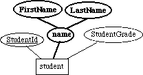
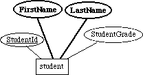
    The student entity from the ER diagram (Figure 15) of module "Entity-Relationship Model" also is not in 1NF because its name attribute is a composite, having two subattributes of FirstName and SecondName (see Figure 3). Thus, name is not atomic valued, which again violates the conditions of being in 1NF. However, it is redundant to store the first name, last name, and entire name. As Figure 4 shows, to solve this problem, we eliminate the name attribute and use only the attributes of FirstName and SecondName.

Figure 3  Example of a relation (student) not in 1NF because of a composite attribute, name


Figure 4  Normalization of student from Figure 3 into 1NF


    To summarize, to eliminate a multivalued attribute, we create a new entity from the attribute. To eliminate composite attributes, we break the attribute into its component attributes.

Quick Review Questions
Quick Review Question 1  Convert the following ER diagram to 1NF.


Second Normal Form (2NF)

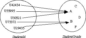
    To discuss Second Normal Form, we need to understand functional dependency. Attribute (or set of attributes) B is functionally dependent on attribute (or set of attributes) A, written A --> B, if for each value of A, there corresponds exactly one value of B. A function exists from A to B. For example, in Figure 4, StudentGrade is functionally dependent on StudentId, written StudentId --> StudentGrade, because given a student's id, we can determine the studentŐs laboratory grade.


However, StudentId is not functionally dependent on StudentGrade. Given a grade, several students might earn that score.

Definition Attribute (or set of attributes) B is functionally dependent on attribute (or set of attributes) A, written A --> B, if for each value of A, there corresponds exactly one value of B.

    Attribute (or set of attributes) B is fully functionally dependent on attribute (or set of attributes) A, if B is functionally dependent on A but is not functionally dependent on any proper subset of A. The entirety of A must be specified for B to be determined. With the primary key (StudentId) consisting of only one attribute, StudentGrade is clearly fully functionally dependent on StudentId.

Definition Attribute (or set of attributes) B is fully functionally dependent on attribute (or set of attributes) A, if B is functionally dependent on A but is not functionally dependent on any proper subset of A.

    As an example where full functional dependency does not hold, suppose that over the years, many different lab sections perform the same physics drag experiment. For example, the class might be for non-majors or majors. Because of data comparisons, one might want to store this information in an attribute (CourseType). Figure 5 contains the ER diagram for this entity with primary key consisting of the collection of fields CatalogNumber, year, semester, and section. The attribute CourseType is functionally dependent, but not fully functionally dependent, on the key, because the catalog number is sufficient to specify the course type, or CatalogNumber --> CourseType. Consequently, we have redundant data. For example, two different sections of course Phys. 201 of necessity are of the same course type, say non-major. When inserting their rows in the table, we must repetitively designate the same type (non-major) for every section of Phys. 201. An insertion anomaly exists.

Figure 5  LabSection with attribute CourseType entity not in 2NF


    A relational database is in Second Normal Form (2NF) if it is in 1NF and each attribute that is not a primary key is fully functionally dependent on the entity's primary key; that is, non-primary key attributes are dependent on the entity's entire primary key. Thus, LabSection with attribute CourseType of Figure 5 is not in 2NF. The problem comes from an attribute that is attached to the wrong entity. Perhaps, we must create a new entity to place the attribute properly. For example, to normalize LabSection of Figure 5 to 2NF, we could have a catalog entity with attributes CatalogNumber and CourseType (see Figure 6).

Definition A relational database is in Second Normal Form (2NF) if it is in 1NF and each attribute that is not a primary key is fully functionally dependent on the entity's primary key.

Figure 6  Normalization of LabSection with attribute CourseType from Figure 5 into 2NF.


Quick Review Questions
Quick Review Question 2  Write all full functional dependencies for the ER diagram below. The genus and species of the plant determine the type of fruit, flower arrangement, leaf arrangement, and leaf shape. GenusDescription is the translation from the Latin or the meaning of the genus name:


Quick Review Questions
Quick Review Question 3  Convert the ER diagram of Quick Review Question 2 to 2NF.


Third Normal Form (3NF)

    A relational database is in Third Normal Form (3NF) if it is in 2NF and no non-primary key attribute is functionally dependent on another non-primary key. To normalize, we move both attributes into a new entity.

Definition A relational database is in Third Normal Form (3NF) if it is in 2NF and no non-primary key attribute is functionally dependent on another non-primary key.

Example 1    Example 1 of the "Relational Database" module considers a chemical database. Suppose the ChemExperiment entity incorrectly also included attributes for the solvent's freezing point (FreezingPoint) and freezing point depression constant (Kf), as the following ER diagram illustrates:
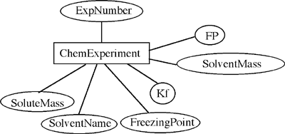

ChemExperiment is not in 3NF because FreezingPoint and Kf are functionally dependent on SolventName, which is not a primary key.
SolventName --> FreezingPoint
SolventName --> Kf
To normalize the entity to 3NF, we move attributes SolventName, FreezingPoint, and Kf into another entity, ChemSolvents, and keep SolventName as an attribute of ChemExperiment, as the following diagrams:
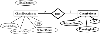

The resulting ER diagram agrees with the schema design in Example 1 of the "Relational Database" module.

Quick Review Questions
Quick Review Question 4  Quick Review Question 1 of module "Relational Databases" described a psychology database that store data from a number of experiments. Suppose the entity PsyExp for a conditioning experiment with a rat has attributes for time, event, and event code, with data and ER diagram as follows:

0.10 2 Right press
1.48 2 Right press
1.48 5 Pellet delivery
3.57 2 Right press
4.72 1 Left press
4.72 5 Pellet delivery

Why is the entity not in 3NF? Normalize the entity to 3NF.

    There are other normal forms, but 3NF is usually sufficient to ensure a correct design. Thus, we say normalization of a data model is the process of converting the model to 3NF. Table 1 summarizes the normal forms along with conversion mechanisms.

Definition Normalization of a data model is the process of converting the model to 3NF.


Table 1.  Normal forms

Normal Form Characteristics Conversion Process
1NF Single-valued attributes Create new entity from multivalued attribute
  Atomic-valued attributes Break composite attribute into component attributes
2NF 1NF Convert to 1NF
  Non-primary key attributes fully functionally dependent on primary key Attached non-primary key attribute to correct (perhaps new) entity
3NF 2NF Convert to 2NF
  No non-primary key attribute is functionally dependent on another non-primary key Move both attributes into a new entity


Logical Relational Database Design

    We use a normalized conceptual database design in the conversion to a logical relational database design. Each entity in the conceptual database design corresponds to a table in the logical database design. Entity attributes become the table columns with conceptual database primary keys mapping directly to logical database primary keys.

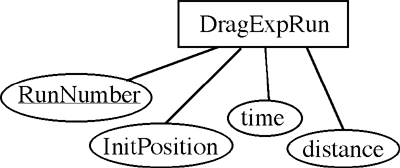
Example 2    The entity DragExpRun of ER diagram (Figure 15) of module "Entity-Relationship Model", which Figure 7 below reproduces, maps to the following relation with primary key RunNumber:

DragExpRun
RunNumber InitPosition time distance
... ... ... ...

Figure 7.  Entity DragExpRun of ER diagram (Figure 15) of module "Entity-Relationship Model"

Quick Review Questions
Quick Review Question 5  Develop the table corresponding to the entity student from Figure 4.

Example 3    The entity LabSection from Figure 2 has 1-to-N relationship with DragRunExp from Figure 7 because a lab section assigns many runs of the drag experiment. Thus, in the DragRunExp relation, we have a foreign key of the primary key of LabSection, which is a collection of CatalogNumber, year, semester, and section. The table configuration follows:

DragRunExp
RunNumber InitPosition time distance Catalog-Number year semester section
... ... ... ... ... ... ... ...

Quick Review Questions
Quick Review Question 6  Revise the DragRunExp relation to reflect the fact that team with primary key TeamNumber and additional attribute of TeamGrade has a 1-to-N relationship with DragRunExp.


    A 1-to-1 relationship does not occur very often. Sometimes, such a relationship implies that we should collapse the two entities into one. If not, we treat the relationship as we did with 1-to-N relationships by making the primary key of one entity a foreign key in the other.

Example 4    In ER diagram (Figure 15) of module "Entity-Relationship Model," entity student is related to entity team with two relationships, one of which is a 1-to-1 LeaderOf relationship (see Figure 8). To convert to the logical database model, in team we make StudentId a foreign key with attribute name LeaderStudentId. The value of this attribute is the student id of the team leader. The table configuration for team follows:

team
TeamNumber TeamGrade LeaderStudentd
... ... ...

Figure 8.  Entities student and team and their attributes and relationships from ER diagram (Figure 15) of module "Entity-Relationship Model"
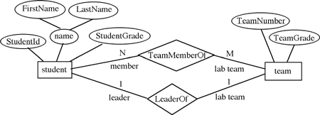


    For an M-to-N relationship maps, we create a new junction entity, where each of the original entities is related to the junction entity with a 1-to-N relationship. Thus, each original entity value is related to many junction entity values. If a primary key is not obvious for the junction entity, we use a collection of the primary key attributes of the original entities as the primary key in the junction entity.

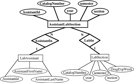
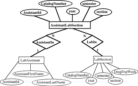
Example 5    The assistant and LabSection entities of Figure 2 have an N-to-M relationship, assists. As Figure 9 illustrates, we create a new AssistantLabSection entity that has the primary keys from both assistant and LabSection. A 1-to-N relationship exists from assistant to AssistantLabSection and from LabSection to AssistantLabSection. The corresponding junction table is as follows:

AssistantLabSection
AssistantId CatalogNumber year semester section
... ... ... ... ...


Figure 9.  Resolving of N-to-M relationship of Example 5


Quick Review Question
Quick Review Question 7  Resolve the N-to-M relationship of student Figure 2 and LabSection of Figure 4 into a relation.


    In summary, to start the conversion of a conceptual database design in 3NF to a logical relational database design, we perform the following mappings:

Exercises

For each of Exercises 1-4 from module "Entity-Relationship Model," do the following:

    a. Normalize the conceptual data model
    b. Map Part a to a logical relational database model

1. Exercise 1 2. Exercise 2
3. Exercise 3 4. Exercise 4

5. a. Convert the N-to-M relationship TeamMemberOf from student to team to have only 1-to-N relationships in the ER model.
   b. Map Part a into relations.
6. Develop the table corresponding to the entity LabSection from Figure 2.


Copyright © 2002, Dr. Angela B. Shiflet
All rights reserved